|
|
|
|
|
|
Braze Technologies
|
|
|
|
|
|
|
|
Innovative solutions
for the "classic" arcade collector |
|
|
|
|
|
| Missile Command Multigame Kit -- Installation
Guide |
Before installing this kit, make sure your Missile Command game is fully
functional. The Multigame kit can only work on a fully functional
Atari Missile Command board. This is a good time to enter test mode, make
sure the RAM test passes, make sure the test mode screen does not indicate any
other failures. Then exit out of test mode, make sure game play, switches, and
game sounds are all working correctly. You are now ready to start the
installation.
Turn your game off and locate the main game PCB. Refer to the Missile Command
manual for the location of this boardset. For MC upright, the game PCB is
usually attached to the right side of the cabinet (as viewed from the back). The
board may have a screw attaching the boardset to the side of the cabinet, which
will need to be removed so that the boardset can be removed for easy access.
When removing the boardset it is recommended that you label the connector faces
with something like "parts side" or "solder side" to insure when re-installing
the boardset that everything gets re-hooked up correctly.
| Click images for a larger view |
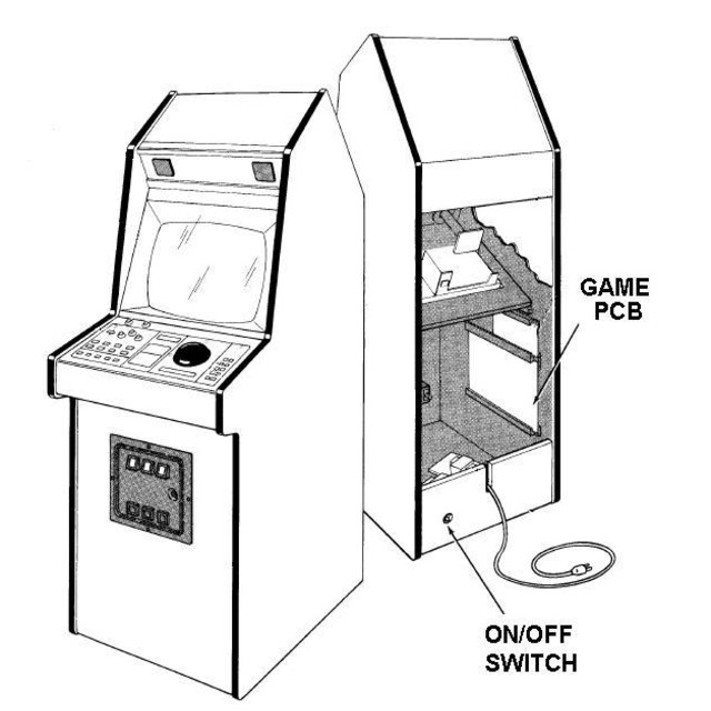
PCB location |
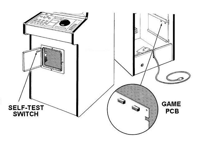
PCB location |
| Click images for a larger view |
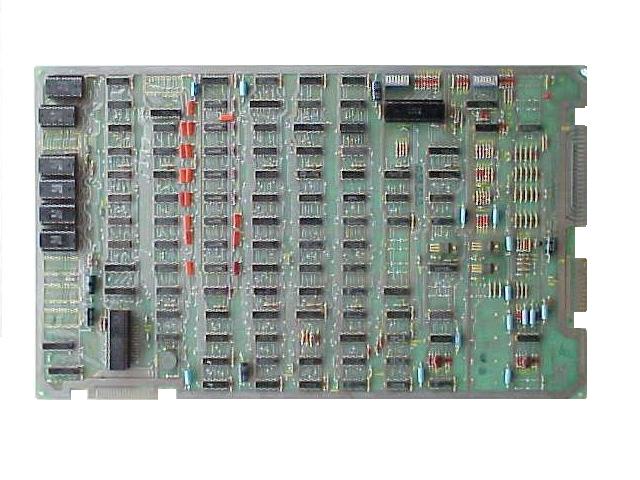
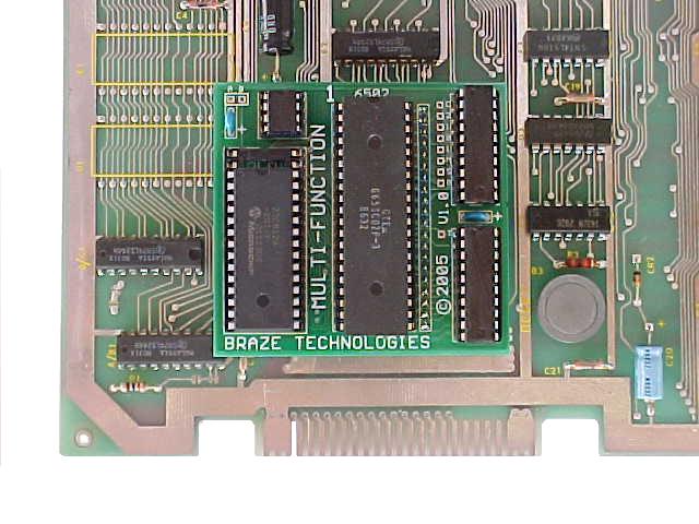
Missile Command PCB |
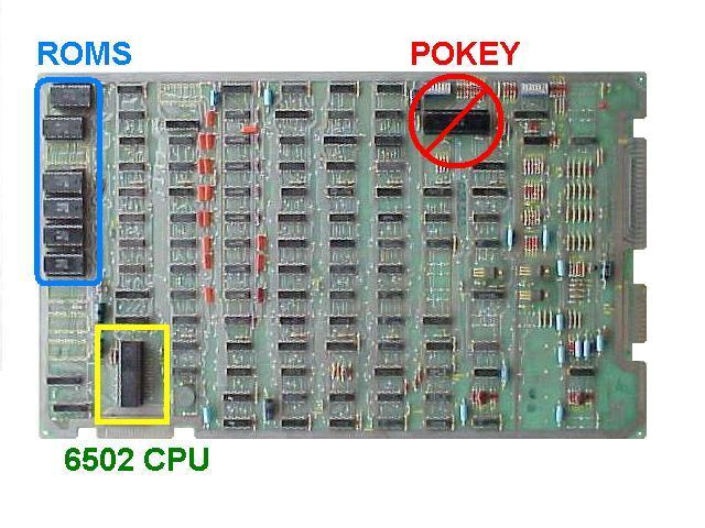
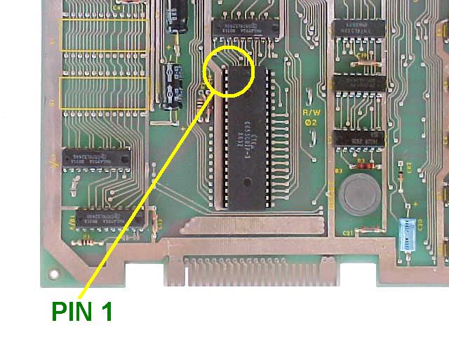
6502 CPU Location |
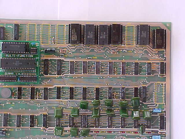
Locate and remove the 6502 CPU chip on the boardset. Use the images below to
assist in locating it. See
6502 Chip Identification for additional information. The 6502 CPU chip is a
40 pin (large) chip, located in the corner of the board at location C2.
See the yellow square in the picture above. Note: there are two 40 pin chips on
the boardset, make sure you remove the 6502 CPU and not the pokey chip.
The 6502 CPU is farthest away from the main edge connector adjacent to the
smaller "catbox" connector. The pokey chip is near the DIPs.
Remove the chip gently by using a flat head screwdriver to pry it out of its
socket from each end. Some of the Atari boardsets have open frame sockets which
do not protect the PCB traces. Be careful not to scratch any of the PCB
traces underneath the socket. Also be careful not to bend any of the pins.
If any pins do get inadvertently bent, you will need to straighten them out
before the next step.
| Click images for a larger view |
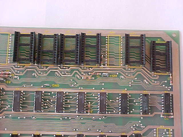
MC 6502 CPU location |
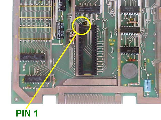
6502 CPU Removed |
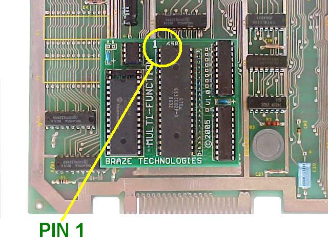
Insert the just removed 6502 CPU chip into the empty 40 pin socket on the
Multigame Kit. Make sure pin-1 is correctly oriented. Pin-1 is marked on the
6502 CPU chip usually by some type of indentation or circle molded into the
plastic. The end of the chip with the marking, needs to match up with the socket
on the daughter card that also has a marking on the plastic. Pin-1 is also
labeled on the kit pcb with a large "1". If the 6502 chip is installed
backwards it will cause permanent damage to the 6502 chip.
| Click images for a larger view |
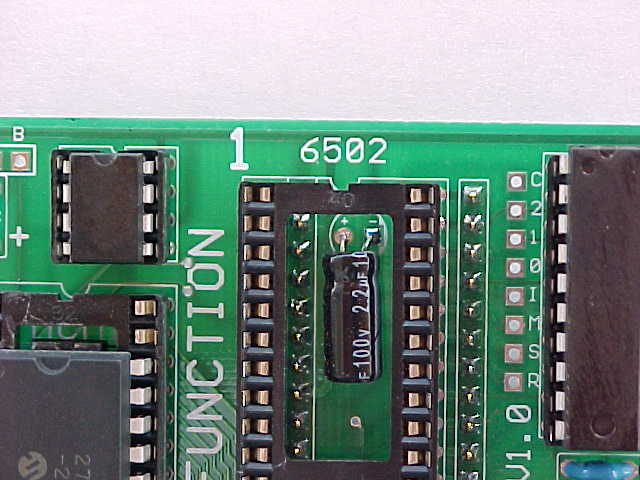
Pin-1 Identification |
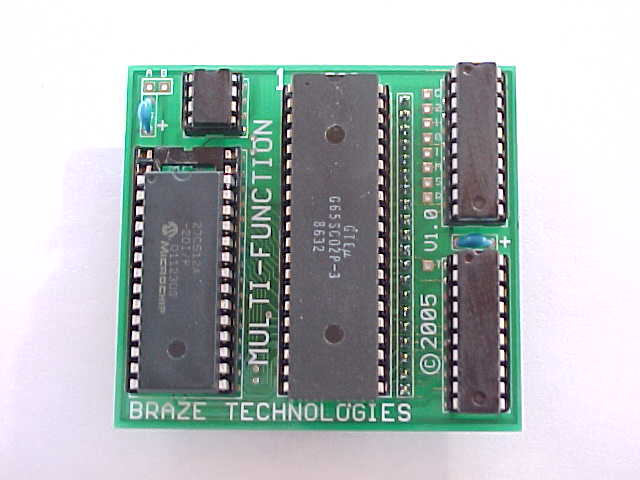
Multigame with 6502 installed |
Insert the CPU daughter card back into the 6502 CPU socket on the boardset
where the 6502 CPU chip was originally removed from. Again, make sure pin-1 of
the 6502/daughter card is oriented to correctly match pin-1 on the boardset.
Pin-1 will be on the inward facing side of the CPU socket. Use the photos as a
guide.
| Click images for a larger view |
Multigame Installed |
Multigame Installed |
Review the steps and double check that 6502 CPU is properly installed into
the daughter card with no bent pins and that it is correctly oriented for pin-1.
Check that the daughter card is also installed snug into the 6052 CPU socket at
C2 with pin-1 matched up. Check to make sure the daughter card is not
inadvertently off by one row such that one pin on each side is off the end of
the socket. REPEAT: If any of these devices are incorrectly installed it may
cause permanent damage to the boardset or kit.
Reinstall your board into the cabinet, hookup the edge connector with the
original orientation and then power up your game. If the game does not come up,
turn power off immediately, double check your work, and read over the
troubleshooting section.
This is a good time to enter test mode and to configure the game
settings to your personal
preference.
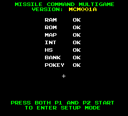
Multigame Self test |
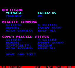
Multigame Setup |
As a side note, if you want, you can also remove the old code eproms, hence
the expression "ROM SAVER". I personally like to remove the eproms so
that the board will consume slightly less power and generate a little less heat.
This however is optional. The eproms are located at the edge of the board near
the 6502 CPU location in row 1. See pictures below. The more common board will
have 6 eproms that can be removed. The lesser common (older style) boards there
will be 11 eproms. 10 along the edge, and 1 eprom on row 3.
It is suggested that this step is done after verifying the multigame is
working. That is because in the
troubleshooting section
one of the procedures depending on the problem is to un-install the kit and
revert it back to plain Missile Command for verification.
| Click images for a larger view |
ROM Locations |
ROMs Removed |
< Prev Page
|