|
||||||||||||||||||||||||||
|
||||||||||||||||||||||||||
|

Asteroids Multigame Kit -- Installation Guide
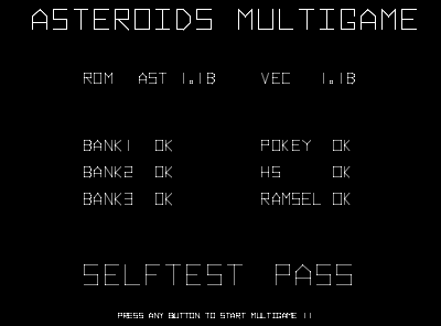
Step 0: Make sure the Asteroids game is fully working!Before installing this kit, make sure the Asteroids game is fully functional. The Asteroids Multigame kit can only work on a fully functional unmodified Atari Asteroids board. If the game board has any special modifications such as speed up hacks, input swaps, it is possible this kit will not function correctly. This is a good time to enter test mode, make sure the RAM test passes, make sure the test mode screen does not indicate any other failures. Make sure the game can enter and exit testmode. Verify that all the game play functions, switches, LEDs, and all game sounds are working correctly. Pay close attention and make sure all the vectors are displayed correctly without any flickering or glitches. It is important to have a solid stable working Asteroids game before installing the kit.You are now ready to start the installation. Note: If the Asteroids board contains the Braze Technologies Asteroids High Score Save Kit then see: how to transfer high scores for instructions on a special one-time procedure for transferring (importing) the high scores from the Asteroids HS save kit to the Asteroids Multigame.
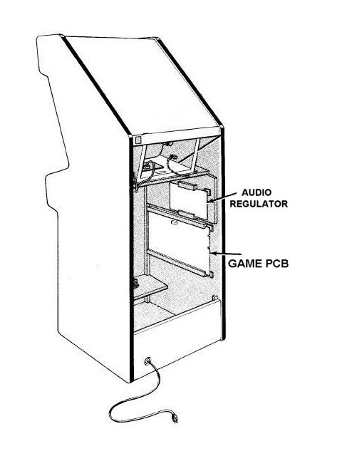
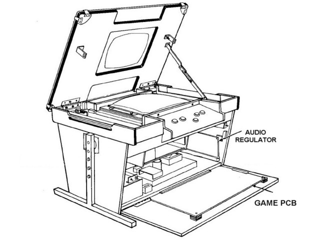
Step 1: Remove the game PCB from the cabinetMake sure the game is turned OFF. Locate the main game PCB. Refer to the Asteroids manual for the location of this boardset. For Asteroids upright and cabaret, the game PCB is attached to the right hand side of the cabinet (as viewed from the back). For Asteroids cocktail, the game PCB is mounted to the back of the access panel. The board may have one more screws attaching the boardset to the side of the cabinet. These screws will beed to be removed so that the boardset can be safely removed for easy access. When removing the boardset it is recommended to label the connector faces with something like "parts side" or "solder side" to insure when re-installing the boardset that everything gets hooked up correctly.Tip: Take your time! Remove the gameboard so the work can be done in a well lighted area. There are two simple solder connections that need to be made so a soldering iron and solder are required. Do not attempt to install this kit without removing the gameboard from the cabinet.
Step 2: Locate and remove the 6502 CPU chip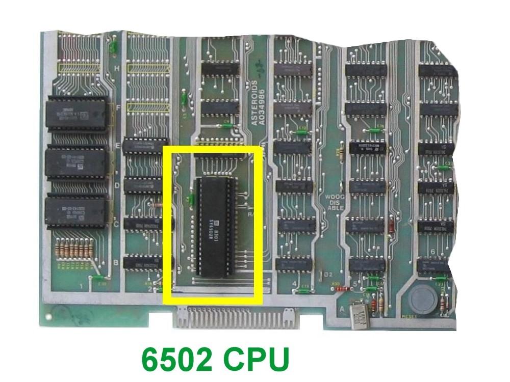
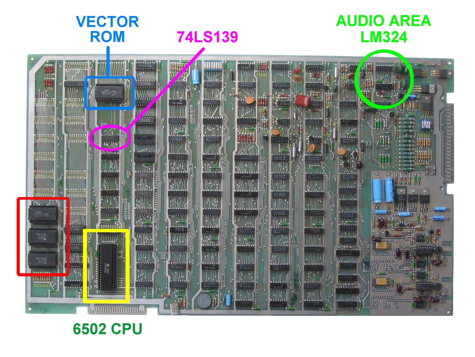
Locate and remove the 6502 CPU chip on the boardset. Use the images below to assist in locating it. See 6502 Chip Identification for additional information. The 6502 CPU chip is a 40 pin (large) chip, located in the corner of the board at location C3. It is the only 40 pin chip on the boardset and on some earlier revisions is located in column 2. See the yellow square in the picture above. It is adjacent to the smaller "catbox" connector. Gently remove the 6502 chip by using a flat head screwdriver to pry it out of its socket from each end. Caution: Some of the Atari boardsets have open frame sockets which do not protect the PCB traces. Be careful not to scratch any of the PCB traces underneath the socket. Be careful not to bend any of the pins. If any pins do get inadvertently bent they will need to straightened out before the next step.
Step 3: Insert the 6502 CPU into the Multigame Kit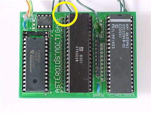
Insert the just removed 6502 CPU into the empty 40 pin socket on the Multigame Kit. Make sure pin-1 is correctly oriented. Pin-1 is marked on the 6502 CPU chip by some type of indentation or circle molded into the plastic. The end of the chip with the marking, needs to match up with the socket on the daughter card that also has a marking on the plastic. Pin-1 is also labelled on the kit pcb with a large "1". If the 6502 chip is installed backwards it may cause permanent damage to the 6502 chip or the multigame.
Step 4: Insert the Multigame CPU into the boardset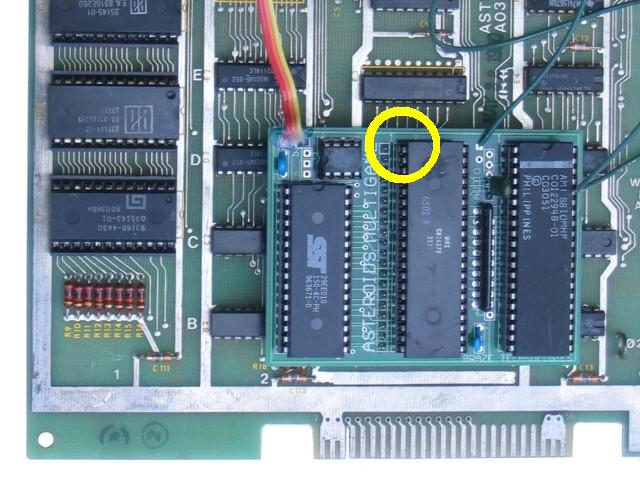
Insert the mulitgame CPU daughter card into the 6502 CPU socket on the Asteroids boardset where the 6502 CPU chip was originally removed from. Check to make sure pin-1 of the 6502/daughter card is oriented to correctly match pin-1 on the boardset. Use the photos as a guide. Be careful not to bend any of the tiny pins on the multigame. Do not force the multigame into the socket.
Step 5: Locate and remove the vector ROM chip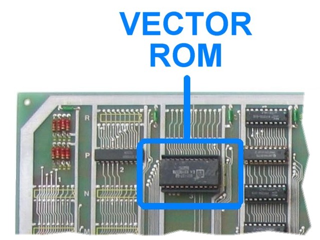
Locate and remove the Asteroids vector ROM chip on the boardset. The vector ROM is located at grid location N/P3 and is a 24 pin device usually on the same column as the 6502 CPU. On some earlier revisions this chip is located in column 2. Remove the chip gently by using a flat head screwdriver to pry it out of its socket from each end just like done in step 2 when removing the 6502 chip. The Asteroids vector ROM chip is not used once the multigame is installed. It is suggested to save this chip in the Multigame antistatic bag. It may be needed for trouble shooting and if ever the Multigame kit is to be uninstalled and reverted back.
Step 6: Locate pin-20 of unpopulated socket at R3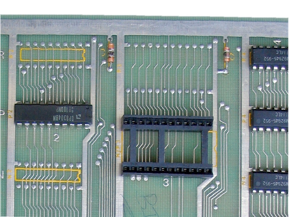
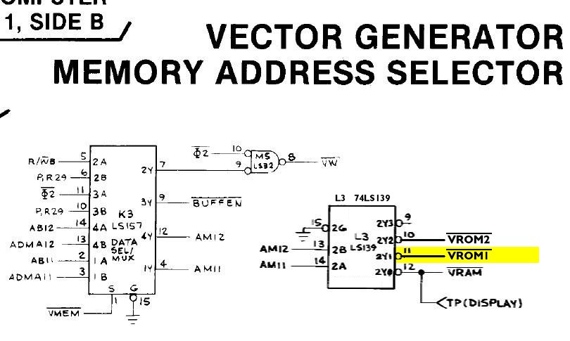
Next to the vector eprom socket should be an unpopulated vector socket at board location R3. Counting carefully, locate pin-20 of this unpopulated socket. The unpopulated R3 vector rom socket layout has 24 pins. Use the photo as a guide. It is important that this signal is correctly located as the multigame vector wire will attach to this hole. This signal corresponds to schematic signal VROM1. Tip: Prepare this hole for soldering. Using a solder sucker or solder braid, remove the solder in the hole of pin-20. This is best done before inserting the Multigame vector pcb in order to have full access to this pin. The vector daughter card will partially over this pin.
Step 7: Attach the VROM1 wire to the boardset
The short wire from the Asteroids Multigame vector board will need to be soldered to the asteroids PCB. This signal corresponds to schematic signal VROM1. This signal is an output of the 74LS139 chip at L3 pin-11. On most asteroids boards this signal is only accessible in two places. One where the signal originates directly on this 74LS139 chip and the other at pin-20 of the the unpopulated 24-pin vector socket as identified in the previous step. The VROM1 signal trace only follows the top of the PCB and there are no via holes on this signal trace. Solder this wire into the pin-20 hole of the unpopulated vector rom socket. Solder the wire from the vector daughter card into this hole on the solder side of the PCB and clip off any excessive wire that pokes through. Inspect your work, checking to make sure the wire is in the correct pin location and that the solder joint is good and that there are no solder shorts or excess solder blobs. Alternate location for VROM1 If for some reason the VROM1 signal (hole) is not accessible on the unpopulated vector socket, then the mulitgame vector wire will need be attached directly to pin-11 of the 74LS139 chip at L3. In this case carefully clean pin-11 of the 74LS139 chip. Then place (melt) a small solder dab on pin-11. Solder tin the vector wire on the multigame kit by placing a small solder dab on it. Then solder the vector wire to pin-11 of the 74LS139 making a strong physical and electrical connection. This alternate method should only be used if the VROM1 signal (hole) on the spare vector socket cannot be used.
Step 8: Insert the Vector board into the boardset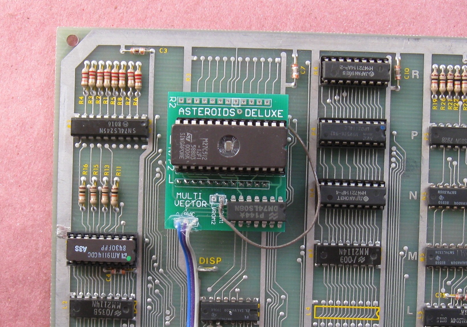
Install the vector daughter card into the N/P3 socket. Make sure no pins get inadvertently bent and make sure that no pins overlap the ends of the socket. At this point both Multigame pcbs should be installed into their respective sockets. You may want to use a few strips of tape to secure the wires to the board so that they do not easily get caught or snag on something. The long audio wire still needs to be attached and that is covered later.
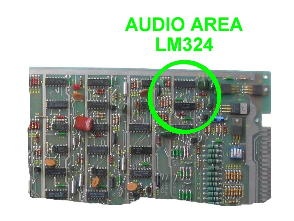
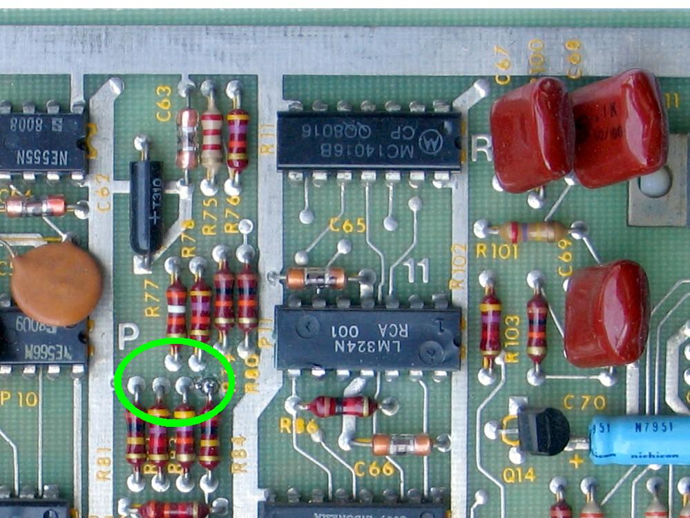
Step 9: Locate the LM324 audio amp chip at P11
Locate the LM324 audio amp which is located in the audio
section of the Asteroids board.
On the most Asteroids boards, this chip is located at grid
location P11.
The audio wire from the Asteroids Multigame CPU board will
connect to the schematic signal that is pin-9 of the LM324.
This provides a connection between the POKEY chip on the
Asteroids Multigame kit and the input to audio pre-amp on the Asteroids board.
As seen in the schematic, this signal is also connected to several nearby resistors. Using the photos locate the cluster of 6 resistors that are connected to pin-9 of the LM324. Select one of those resistor and attach the long audio wire from the asteroids multigame to the common end shared by this group of resistors.
Tip: Since the audio wire is long, it is suggested to secure it to the Asteroids board or neatly tuck it around the chips such that it does not dangle or snag on anything. One way to do this, is to 'thread' the wire underneath a few components on its way from the kit to the LM324 audio area. Start at the kit, thread the wire through the GND test point at grid location J4. From there, thread the wire down and around the RAM chip at P3. Continuing toward the audio area, thread the wire underneath the electrolytic capacitor at C19 next to the DIP switch. Continuing toward the audio area there are several other capacitors which you can selectively thread the wire through until the wire is within a few inches of the LM324 area, Alternatively you can use tape or a glue gun to attach the wire to the pcb in order to keep things tidy.
Step 10: Solder the audio wire to LM324 resistor cluster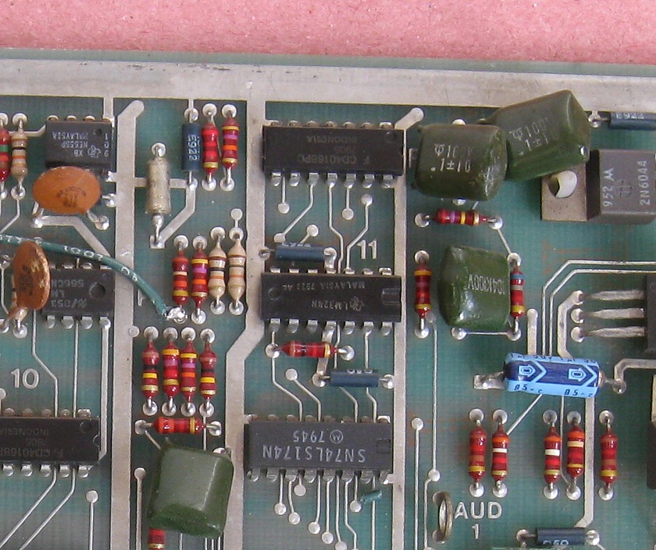
If needed, cut the audio wire to a shorter length such that there is not any excess wire. Place a small solder dab on the resistor cluster where the audio wire is going to be attached and also solder tin the wire before crimping it around the resistor. This will make for a cleaner and stronger connection. It is suggested to loop the wire underneath one of the resistors and secure it to the resistor lead without shorting to any other component. Check your work afterwards to make sure the wire is soldered to the correct group of resistors and that there are not any shorts between them. Use a magnifying glass for an up close look. Congratulations - This completes the Asteroids Multigame kit installation process! Alternate location for audio wire Alternatively this long wire can be connected directly to pin-9 of the LM324. This method should only be used if the wire is unable to be connected to the cluster of resistors.
Step 11: Double check your workReview the steps and double check that 6502 CPU is properly installed into the daughter card with no bent pins and that it is correctly oriented for pin-1. Check that the daughter card is also installed snug into the 6052 CPU socket at C3 with pin-1 matched up. Check to make sure the daughter card is not inadvertently off by one row such that one pin on each side is off the end of the socket. Repeat the checks for the vector board. Examine the solder connections looking for any cold or broken solder connections or any solder shorts. REPEAT: If any of these devices are installed incorrectly it may cause permanent damage to the boardset or kit.
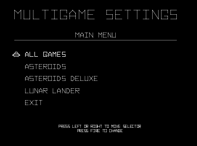
Step 12: Power-up the game and enjoy!Re-install your board into the cabinet, hookup the edge connector with the original orientation and then power-up your game. This is a good time to review the power-up selftest description.After the game has booted up and appears to be working that is a good time to enter testmode and to configure the game settings to your personal preference. If the game does not come up, turn power off immediately, double check your work, and read over the trouble shooting section and the power-up selftest description. Note: If you are transferring your Asteroids high scores from a previously installed Asteroids High Score Save Kit review the transferring high scores procedure.
Step 13: Optional - Remove the CPU ROMS - "ROM SAVER"As a side note, if you want, you can also remove the original AST CPU eproms, hence the expression "ROM SAVER". I personally like to remove the eproms so that the board will consume slightly less power and generate a little less heat. This however is optional. The three eproms are located at the edge of the board near the 6502 CPU location in row 1.It is suggested that this step is done after verifying the Asteroids Multigame is working. That is because in the trouble shooting section one of the procedures depending on the problem is to un-install the multigame kit and revert it back to Asteroids for verification. |
|||||||||||||||||||||||||
|
|
||||||||||||||||||||||||||
