|
||||||||||||||||||||||||||||||||||||||||||||||||||||||
|
||||||||||||||||||||||||||||||||||||||||||||||||||||||
|
Step 0: Make sure your Millipede game is fully workingBefore installing this kit, make sure your Millipede game is fully functional. Make sure there are no beeps when the game powers up, and make sure that you can enter and exit test mode, and that test mode does not report any errors. This kit can only work in a fully functional game. Step 1: Turn off power to the gameWhile it may be possible to install this kit without removing your board from its cabinet, you may find it easier to install the kit if you do remove the board. In that case, pay careful attention (or label), any wire connections as you disconnect your board so that you can correctly reconnect the game PCB afterwards. Take note of which side of the PCB edge connectors are facing the parts side of the board and which sides face the solder side, These connectors are typically not keyed and can be inadvertently plugged in backwards - ouch! It is recommended that you label the connectors face with something like "parts side" or "solder side". Step 2: Remove the game PCB from the cabinetFor Millipede upright, the game PCB is usually attached to the right side of the cabinet (as viewed from the back). It is commonly enclosed in a large metal cage. The board may also have screws attaching the boardset to cabinet or cage, which will need to be removed so that the boardset can be removed for easy access. Refer to your game manual for additional information about locating and removing the game PCB. 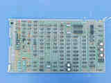
Millipede game PCB Step 3: On the PCB, locate and remove the 6502 CPU chipLocate and remove the 6502 CPU chip on the boardset. Use the images below to assist in locating it. The 6502 CPU chip is a 40 pin (large) chip, located in Row 2 There are three 40 pin chips in a cluster near the corner of the boardset. Remove only the 6502 CPU. Use the photos as a guide to help locate the chip. Remove the chip gently by using a flat head screwdriver to pry it out of its socket from each end. Some of the Atari boardsets have open frame sockets which do not protect the PCB traces. Be careful not to scratch any of the PCB traces underneath the socket. Also be careful not to bend any of the pins. If any pins do get inadvertently bent, you will need to straighten them out before the next step. Needle nose pliers work best for this.
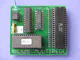
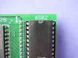
Step 4: Insert the 6502 CPU into the larger daughter cardInsert the just removed 6502 CPU chip into the empty 40 pin socket on the larger daughter card in the Multipede Kit. Make sure pin-1 is correctly oriented. Pin-1 is usually indicated on the 6502 CPU chip by some type of indentation or circle molded into the plastic. Pin-1 on the daughter card is marked by a large "1" on the PCB, as well the with the text "6502". If the 6502 chip is installed backwards it will cause permanent damage to the 6502 chip.
Step 5: Insert the daughter card into the boardsetInsert the daughter card back into the 6502 CPU socket on the boardset where the 6502 CPU chip was originally removed from. Again, make sure pin-1 of the 6502/daughter card is oriented to correctly match pin-1 on the boardset. Use the photos as a guide. The kit fits very close to the test points that stick up out of the PCB. Make sure the test point tabs remain on the outside of the daughter card and that they do not not short against the underneath side of the daughter card. You may need to slightly bend the closest test point. The gold machined pins on the daughter can bend very easily, make sure they are all straight and that each pin is inserted in the Millipede socket.
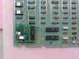
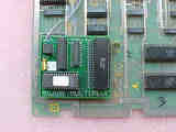
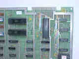
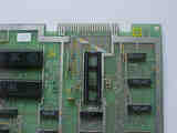
Click image for larger view Step 6: Locate and remove the character set eproms 5P and 5ROn the game board, locate the two character set eproms. They are located a locations 5P and 5R, and are usually labeled with "106" and "107" on the stickers. Use the photos as a guide. Remove these two eproms following similar steps and precautions as in step 3, again, being careful not to scratch the Millipede PCB traces. These chips will not be reused. If you chose to keep them, it is suggested that they be stored in the anti-static bag provided with the kit.
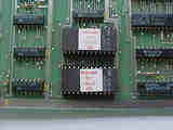
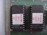
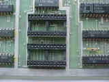
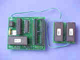
Click image for larger view Step 7: Insert the smaller daughter card into sockets 5P and 5RWith chip sockets 5P and 5R now empty, insert the smaller daughter card into those sockets. Pay attention that the pins are aligned with the socket. This is sort of tricky, as the daughter card has a two 28 pin eproms on the top side, but only two sets of 24 pins on the bottom side. (Actually 23 pins per device, as it is normal for one of the pins to be clipped on each device). The wires coming from the daughter card should be on the side closest to the main CPU daughter card inserted in step 4. The Wire-Wrap sockets used on the smaller daughter card may have tall pins which may have become misaligned. Make sure the pins are straight and that all pins get inserted into the millipede socket. You may have to provide a little bit of force to get a snug fit.
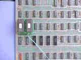
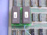
Click image for larger view Step 8: Double check your workReview the previous steps double checking that 6502 CPU is properly installed into the daughter card with no bent pins and that it is correctly oriented for pin-1. And that the daughter card is also installed snug into the 6052 CPU socket at Row 2 with pin-1 matched up. Apply the same checks to the character rom daughter card installed at 5P & 5R as part of steps 6 and 7. REPEAT: If any of these devices are installed backwards it may cause permanent damage to the kit and your boardset!
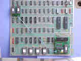
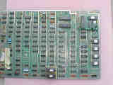
Click image for larger view Step 9: Reinstall game PCB into cabinet and PowerupReinstall your Millipede board into the cabinet, hookup the two edge connectors with the original orientation. Then powerup your game. If the game does not come up, turn power off immediately, double check your work, and read over the trouble shooting section. Step 10: Verify Multipede functionalityThe game should have powered up in Millipede mode. Press both p1-start and p2-start and verify the game toggles to Centipede. Repeat and verify it toggles back to Millipede. Now is a good time to verify your game settings via the setup menu. Put the game in test mode by sliding the test switch on. You should see a screen similar to the original millipede test mode screen. Follow the on-screen instructions in test mode to press and hold P1-start and P2-start at same time. The game will transition to setup mode. Once in setup mode, verify the settings displayed are the ones desired. To change a setting, use the trackball to move up and down to select the setting to be changed. The selected setting is indicated by a shooter icon on the left. Once selected, use the fire button to toggle though the available combinations. When done making changes to settings, be sure to select "SAVE AND EXIT". At this time the game will return to the multipede test mode screen. Turn the test mode switch off to return to game play mode. The new settings should now be active. Detailed operation of the setup menu can be found here. As a side note, if you want, you can also remove the old code eproms. These are located at the edge of the board near the 6502 CPU location. See code eprom pic1. You can also remove the EAROM if desired. See earom pic1 and earom pic2. Once the Multipede kit is installed, the EAROM and existing CPU ROMs are no longer accessed. < Prev Page |
|||||||||||||||||||||||||||||||||||||||||||||||||||||
|
|
||||||||||||||||||||||||||||||||||||||||||||||||||||||

