|
|
||||||||||||||||||||||||||||||||||||
|
||||||||||||||||||||||||||||||||||||
|
||||||||||||||||||||||||||||||||||||
|
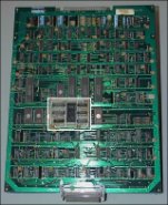
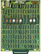
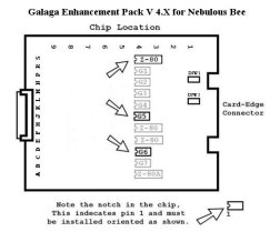
Step 0: Turn off power to the gameIt may possible to install this kit without removing your board from its cabinet, however, you may find it easier to install the kit if you do remove the board. In that case, pay careful attention (or label), any wire connections as you disconnect your board so that you can correctly re-hookup the game PCB afterwards. Take note of which side of the card-edge connector is facing the parts side of the board and which side faces the solder side, This connector is typically not keyed and can be inadvertently plugged in backwards - ouch! It is recommended that you label the connector faces with something like "parts side" or "solder side". Step 1: Locate the CPU boardThere are 2 different types of Clone boards this kit can be installed into. Locate the CPU board for your type of Galaga Board. In general, the installation is the same between board types, only the ROM chip locations are different.
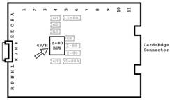
Step 2: For Gallag boards only
Remove the Z-80 sync bus controller at location 4/FH shown below:
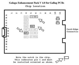
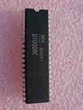
Step 3: Remove the chipsLocate and remove the main Z80 chip, the G5 and G6 chips. Use the diagram or photos to assist in locating them. See Z80 Chip Identification for additional information. The Z80 chip is a 40 pin (large) chip. However there are 4 of them, so remove the one shown in the diagram for your board set. Remove the chips gently by using a flat head screwdriver to pry it out of its socket from each end. Be careful not to bend any of the pins. If any pins do get inadvertently bent, you will need to straighten them out before the next step. Needle nose pliers work the best for this.
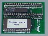
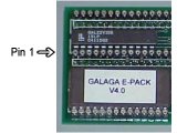
Step 4: Insert the Z80 into the daughter cardInsert the just removed main Z80 chip into the empty 40 pin socket on the Galaga Enhancement Pack. Make sure pin-1 is correctly oriented. Pin-1 is marked on the Z80 chip usually by some type of indentation or circle molded into the plastic. The end of the chip with the marking, needs to match up with the socket on the daughter card that also has a marking on the plastic. There should also may be a small sticker on the daughter card marking pin-1.
Step 5: Insert the daughter card into the CPU boardInsert the daughter card back into the Z80 socket on the CPU board where the Z80 chip was originally removed from. Again, make sure pin-1 of the Z80/daughter card is oriented to correctly match pin-1 on the CPU board. Use the photos as a guide. The header on the daughter board has pins that are more heavy duty than the original Z80 pins, thus you will need to press very firmly to get the daughter card to be fully inserted into the original Z80 socket. Step 6: Install the replacement chipsInstall the replacement chips, labeled G5 and G6, where the original chips were removed from. Use the above diagrams again to locate the correct sockets on the board. Take care while inserting the chips and avoid bending any pins. Step 7: Gallag boards onlyReinstall the Z-80 Sync Bus Controller the same way it was removed. HINT: The notches on all the chips face towards the bottom of the board as oriented above. Step 8: Double check your workReview the steps and double check that Z80 is properly installed into the daughter card with no bent pins and that it is correctly oriented for pin-1. And that the daughter card is also installed snug into the Z80 socket with pin-1 matched up. Do the same with any of the chips you replaced. Step 9: Reinstall CPU, power-up game and enjoy!Reinstall your board into the cabinet if necessary, and then power-up your game. Flip the test switch inside the coin door to enter setup mode, or the game will automatically transition to game-play mode. If the game does not come up, turn power off immediately, double check your work, and read over the trouble shooting section. < Prev Page |
|||||||||||||||||||||||||||||||||||
|
|
||||||||||||||||||||||||||||||||||||

