|
|
|
|
|
|
|
|
|
Braze Technologies |
|
|
|
|
|
|
|
Innovative solutions for the "classic" arcade collector
|
|
|
|
|
|
Red Baron High Score Save Kit -- Installation
Guide
Note: Work in progress. This document adopted from the battlezone
instructions
Step 0: Make sure your game is fully workingBefore installing this kit,
make sure your Red Baron game is fully functional. This kit can only work in a
fully functional game.
Step 1: Turn off power to the gameWhile it may be possible to install
this kit without removing your board from its cabinet, you will find it easier
to install the kit if you do remove the board. Pay careful attention (or
label), any wire connections as you disconnect your board so that you can
correctly rehookup the game PCB afterwards. Take note of which side of the PCB
edge connector is facing the parts side of the board and which side faces the
solder side, The connectors are sometimes not keyed and can be inadvertantly
plugged in backwards - ouch! It is recommended that you label the connector
faces with something like "parts side" or "solder side".
Step 2: Locate and remove the game PCBFor Red Baron upright, the game
PCB is usually attached to the left side of the cabinet (as viewed from the
front). The board may have a screw attaching the boardset to the side of the
cabinet, which will need to be removed so that the boardset can be removed for
easy access.
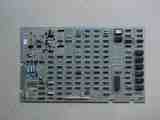
Battlezone main PCB
(6502A Analog Vector Generator)
|
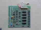
Battlezone AUX Board |
Step 3: Remove the 6502 CPU chipLocate and remove the 6502 CPU chip on
the boardset. Use the images below to assist in locating it. See 6502
Chip Identification for additional information. The 6502 CPU chip is a 40
pin (large) chip, located at M3 It is the only 40 pin chip on the
boardset. Remove the chip gently by using a flat head screwdriver to pry it out
of its socket from each end. Some of the Atari boardsets have open frame sockets
which do not protect the PCB traces. Be careful not to scratch any of the PCB
traces underneath the socket. Also be careful not to bend any of the pins.
If any pins do get inadvertantly bent, you will need to straighten them out
before the next step. Needle nose pliers work the best for this.
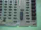
Battlezone 6502 CPU location |
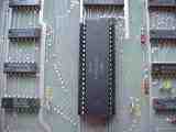
6502 Closeup |
6502 CPU Removed |
Step 4: Insert the 6502 CPU into the daughter cardInsert the just
removed 6502 CPU chip into the empty 40 pin socket on the High Score Save Kit.
Make sure pin-1 is correctly oriented. Pin-1 is marked on the 6502 CPU chip
usually by some type of indentation or circle molded into the plastic. The end
of the chip with the marking, needs to match up with the socket on the daughter
card that also has a marking on the plastic. Pin-1 is also labelled on the kit
pcb with a "1". If the 6502 chip is installed backwards it will cause
permanent damage to the 6502 chip.
Pin-1 Identification
Click images for a
larger view |
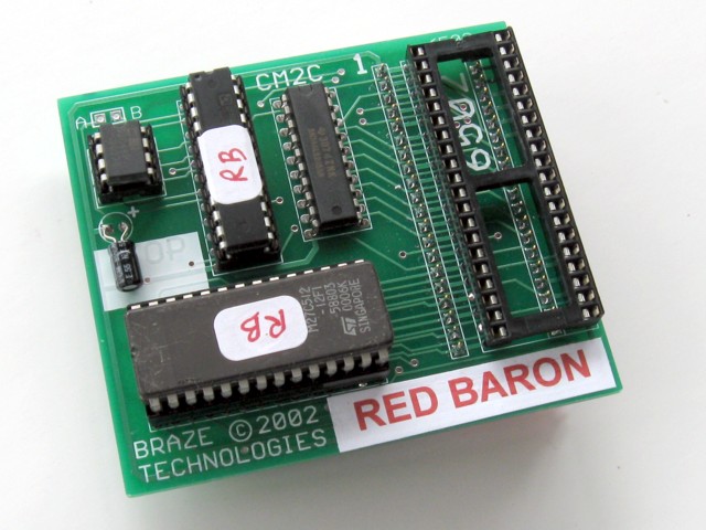
Red Baron HISAVE kit |
Pin-1 Identification |
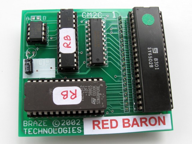
Kit with 6502 installed |
|
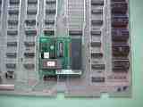
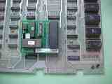
Step 5: Insert the daughter card into the boardsetInsert the daughter
card back into the 6502 CPU socket on the boardset where the 6502 CPU chip was
originally removed from. Again, make sure pin-1 of the 6502/daughter card is
oriented to correctly match pin-1 on the boardset. Use the photos as a guide.
Step 6: Double check your workReview the steps and double check that
6502 CPU is properly installed into the daughter card with no bent pins and that
it is correctly oriented for pin-1. And that the daughter card is also
installed snug into the 6052 CPU socket at M3 with pin-1 matched up.
REPEAT: If any of these devices are installed backwards it will cause
permanent damage to the devices!
Step 7: Powerup and game and enjoy!Reinstall your board into the
cabinet, hookup the edge connector with the original orientation and then
powerup your game.
If the game does not come up, turn power off immediately, double check your
work, and read over the trouble
shooting section.
As a side note, if you want, you can also remove the old code eproms. These
are located at the edge of the board near the 6502 CPU location. See code
eprom picture.
Easy to clear out the high scores when desired. Simply put the game into
selftest (using the cabinet selftest switch). Once in selftest mode, press
(and hold) the start button and the fire button. The screen will imediately
show "ERASED" indicating the high scores have been cleared out. This is a
similar procedure used by other atari games. See Clearing
High Score table for detailed directions.
< Prev Page
|
|


